Hi, my name is Rob and Wolfgang invited me to write this guest post after I sent him pictures of my completed frame.
I didn’t know in advance I was going to write this, so the description below is my best recollection – apologies if there are any slight errors or discrepancies!
This write-up describes opening a computer monitor and exposing mains voltage components. Neither the author nor the website owner recommend anyone carrying this out unless they fully understand the risks involved and take adequate steps to secure the final picture frame. Neither of us take any responsibility for any damage or injury caused as a result of replicating the description below – if in doubt do not do it!
Why it was time to start building my own digital picture frame
We have had a Samsung ‘The Frame’ TV for a few years now and I really like many of its features: much of the time it genuinely looks like a picture hung on the wall, with the ambient light sensor and the virtual ‘mount’ working well – it has fooled a number of visitors. But while it looks good, and is nice and large, the lack of a proper slideshow function and the awkwardness of uploading new images (one at a time through a smartphone app) are definite drawbacks.
When I started to look into alternatives for a digital photo frame for our hallway, I came across this website and was inspired to build my own, for two main reasons: I could build a larger and higher resolution display than generally available, and I could build something that wasn’t dependent on a third-party service to work.
Having seen some good products come and go that then become paperweights because the manufacturer couldn’t afford to keep the online element going I am wary of anything like this.
Tearing down the BenQ PD3200 computer monitor
I wanted at least a 32 inches class display, at 4K resolution, 3:2 aspect ratio, with a seamless flat mount on the wall.
Taking inspiration from Wolfgang’s and Josh’s articles on this website I started looking on Amazon for a display.
As luck would have it I found a BenQ PD3200 listed under Amazon’s “other new and used” for 30% off. It was described as new, damaged (acceptable) but with the damage limited to the bottom/rear. I ordered it, hoping not to have to return it if there was any damage to the actual display, and was pleased to receive a totally undamaged unit (the box was pretty beat up though!). I paired this display with a Raspberry Pi 4 to have 4K support.
Having double-checked that the BenQ panel was indeed fully working, the first job was to disassemble it.
On the rear, there are two screws at the bottom middle to be removed, as well as the four VESA mount screws.

Then the front and rear plastic covers need to be cracked apart – there are two small holes on the bottom edge where you can insert a large flat-bladed screwdriver.

With the monitor face down on a table, I twisted the large screwdriver to start to open up the seam and used a second smaller screwdriver to snap open the seam, sliding the small screwdriver along and repeating (there are small clips every 5cm or so).
Once the rear cover was completely separated, I carefully lifted it up towards the side USB ports – there is a daughter board connected with some cables. Undoing the two screws holding the USB circuit board to the rear cover allowing it to be removed.
In order to remove the front bezel, there are three tiny screws that hold the LED display and control button circuit boards along the bottom edge, removing these, the bezel could be taken off.
Finally, having taken some photos so that I knew where everything plugged in, I carefully unplugged the display, backlight connectors, speakers, and other various cables, peeled back the silver foil, and lifted off the metal cover. I did this carefully as there is a cable underneath that needs unplugging as well. The control and PSU circuit boards can then be unscrewed from the metal cover, and the disassembly is complete.
One of my goals for this project was to have the frame be as shallow as possible, to allow for a nice close fit to the wall – removing the metal cover allows for this, and for the parasitic power supply for the Pi (see below) but it does mean exposing the mains voltage components – please don’t do this unless you are completely comfortable with this, understand the risks involved, and ensure that the final picture frame is mounted in such as way as the mains components can’t be accessed.
Note: You don’t have to completely dismantle the monitor, you can leave the metal box closed. There is a useful document from TÜV Rheinland which, if you scroll all the way down, has photos of all the components.
Display and components assembly
The next step is to assemble all the components for the picture frame and secure them to the panel.
I discarded the USB daughterboard but retained the LED display, the control buttons, the PSU and controller PCBs, the Raspberry Pi, plus a DC-DC power buck. These handy little boards take a range of DC input voltages (typically 24-12v) and step it down to 5v, with convenient screw terminal, DC plug, and USB connectors.
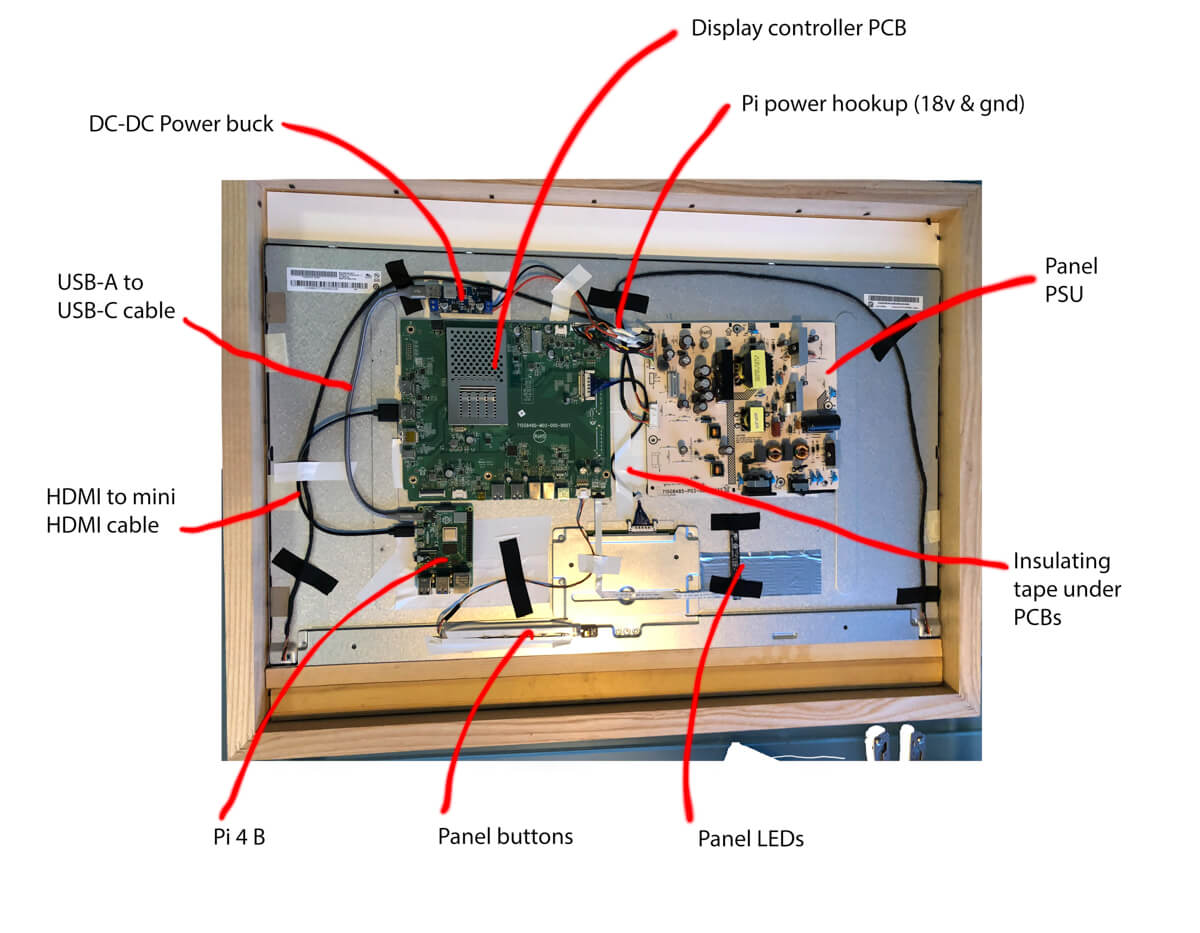
The monitor PSU outputs 18v and 5v – I considered powering the Pi directly from the 5v output but I wasn’t sure whether this would be able to supply the 2A that the Pi needs on top, but I found TÜV documentation saying that the 18v output was rated to 6A.
So I cut one of the 18v and ground lines coming from the PSU and soldered on 18 AWG wires – these are taken to the input terminals on the power buck, and a USB A to USB C cable used to connect the buck to the Pi.
I’m no electrical engineer, so I don’t know whether this is likely to cause long term problems to the display controller board; in my testing so far it seems fine – but do this at your own risk. If you’re willing to have a deeper picture frame, then you can take a much safer and simpler route keeping the metal shroud on the panel, and just using a separate power supply for the Pi.
Note I had originally hoped to power the Pi from the monitors built-in USB hub, but unfortunately, it’s not powered unless it detects a downstream PC attached, even if you enable wake-on-USB in the monitor.
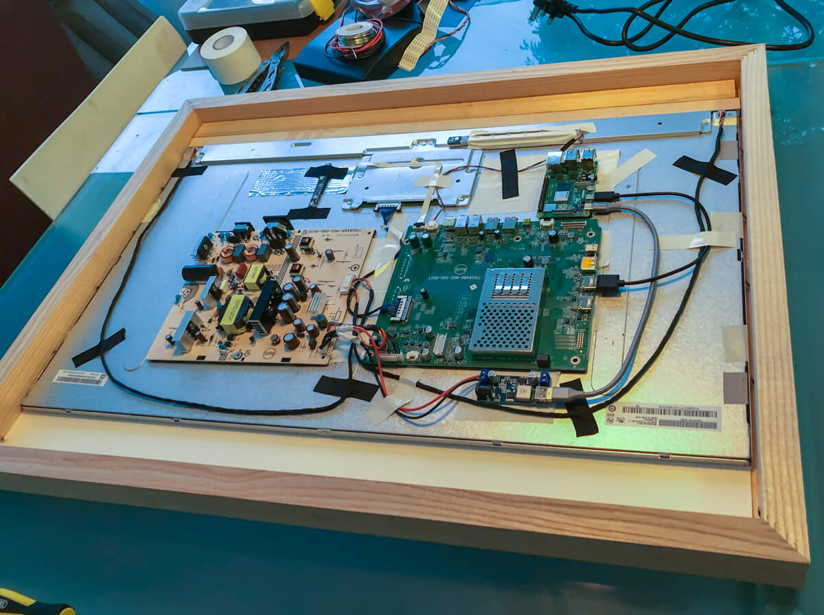
I test arranged the components on the back of the panel, and then used 50mm insulation tape to cover all the areas where components were going to sit. Then I mounted all the components using 2-3 layers of 3M VHB adhesive tape, making sure that there was some clearance between the backside of the PCBs and the panel.
I reconnected all the cables and was ready to test everything. I configured the Pi exactly as per Wolfgang’s instructions.
Calculating the picture frame casing
Once I was sure everything was working, it was time to put it in a picture frame.
I wanted a 3:2 ratio, so I measured the vertical height of the display (tip: do this with an image on the screen, on my panel, with the bezel removed there is a small black portion of the display at the bottom which I didn’t take into account).
Knowing the vertical height, I multiplied by 3/2 to get the horizontal width I needed – this gives the dimensions of the ‘window’ in the mount. I then measured the overall width of the panel (to the outside of the metal surround), subtracted the width of the mount window, and divided by 2 to get the width of the mount border.
Finally adding this border width to the top and bottom of the mount window gives you the overall height.
In summary:
- Mount window height = height of the panel (actual display)
- Mount window width = height of panel * 3/2
- Overall mount width = outside width of the panel
- Overall mount height = overall mount width – mount window width + mount window height
I then used an online picture frame making service to make me a frame and mount using the dimensions above. Note the overall size of the frame will be the overall mount size plus the width of the frame chosen.
I chose a frame with a rebate depth of 38mm, as this was enough to cover the thickness of the panel and the components leaving a few mm for airflow, and I chose a wooden frame for ease of assembly/strengthening.
Once the frame arrived I placed the panel in it – it should fit exactly width-wise – and then lined it up vertically with the window in the mount.
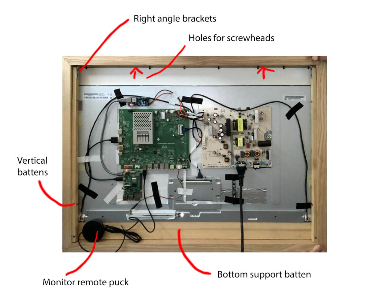
I placed some wooden packing pieces between the bottom of the panel and the bottom of the frame to support the panel in place and then used thin vertical battens on each side to trap the panel in the frame.

The vertical battens were screwed to the inside of the frame to secure them, and for extra strength given the weight of the panel, I screwed right angle brackets to secure the top of the frame to the battens, then screwed through the battens into the bottom packing piece.
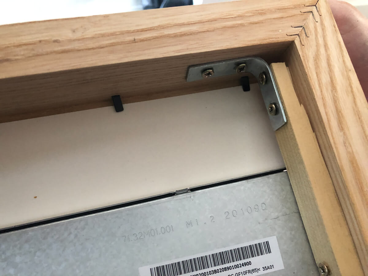
In this way, I wasn’t relying at all on the frame corner connectors to take the weight of the panel.
Mounting it on the wall and hiding the cable
To mount the picture frame flush to the wall, I first took a batten narrower than the width of the frame and screwed two small screws into it to act as hooks.
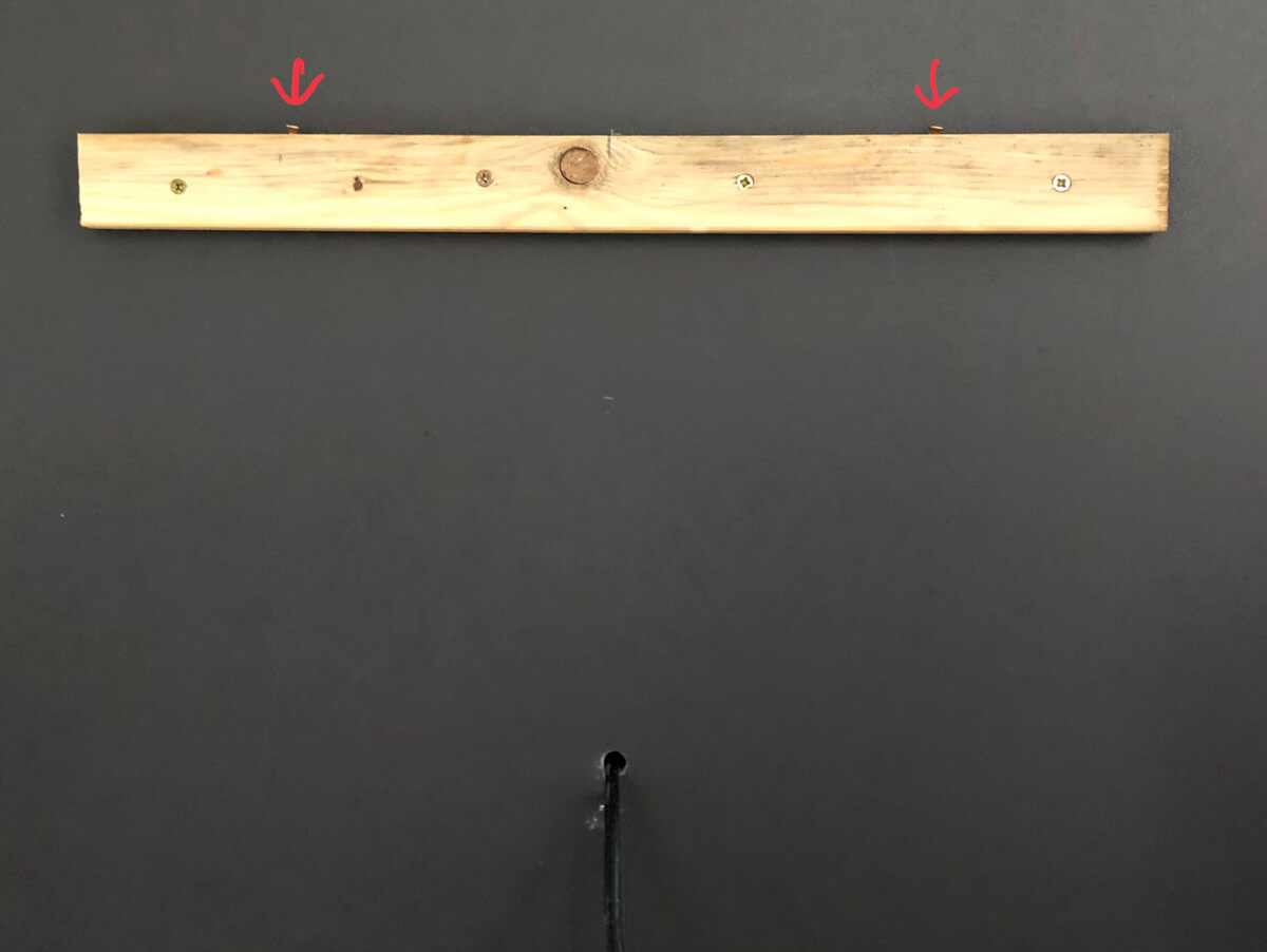
I offered this up to the inside of the top of the frame and marked where the screws went and drilled shallow 8mm holes to accept the heads of the screws – this would allow the picture frame to be ‘hooked’ on to the batten and prevent it being knocked off the wall accidentally. I took care to ensure that the batten was flush with the back of the frame when the screw heads engaged in the holes.
The batten was then fixed to the wall using screws and plugs.
Finally, I drilled a hole through the wall for the power cable – conveniently there is a cupboard behind this particular wall with a mains outlet in it. With the power cable connected to the picture frame, the frame could be hung on the wall by hooking it over the screws in the batten.
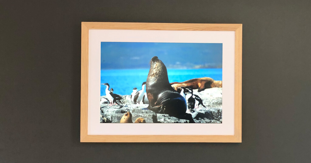
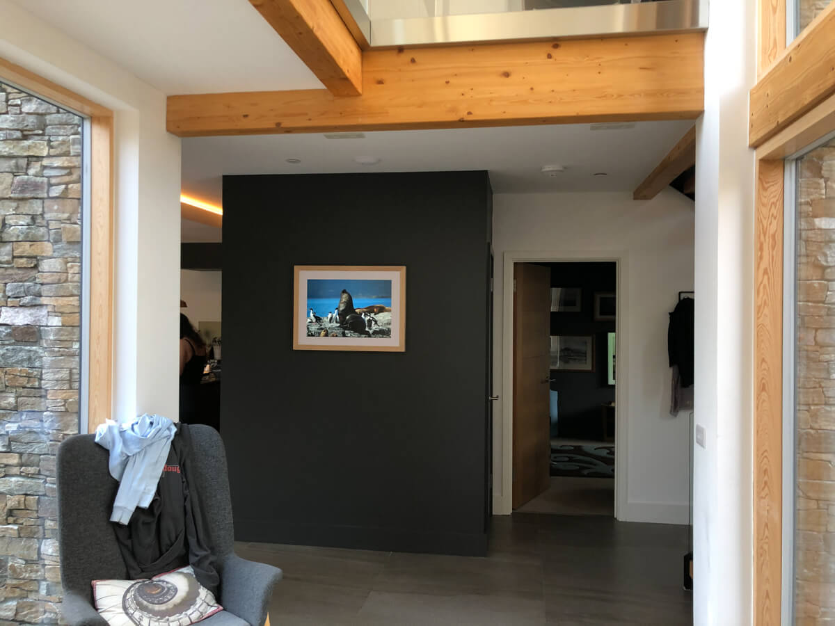
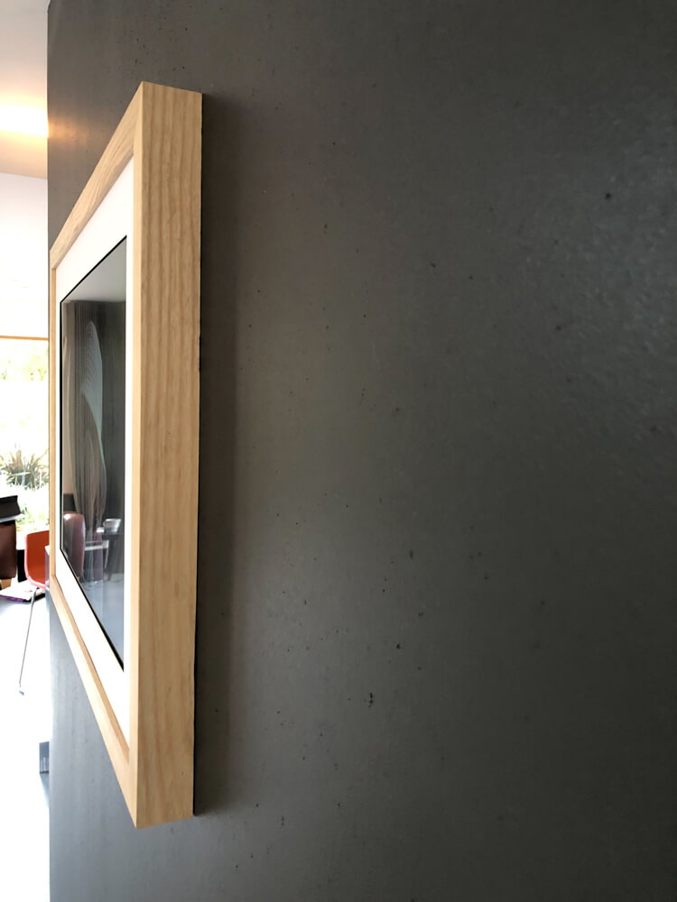
I’m really pleased with the result – it looks incredible and very ‘professional’.
I’ve turned the brightness of the screen down a little – the BenQ screen comes with a USB cabled ‘puck’ which I’ve left plugged in a tucked behind the screen and there’s just enough give in the wall mount to be able to retrieve it to make final adjustments using the display menu.
Ideally, I would like to be able to control the brightness of the screen using the Pi – and couple it to an ambient light sensor, as the brightness required to adequately see the panel in bright daylight results is far too bright for evenings. Unfortunately, at the time of writing the required Linux utility – ddccontrol – is not supported on the Raspberry Pi 4 due to hardware changes. Hopefully, this will be rectified at some point.
Conclusion
Many thanks to Wolfgang and Josh for their write-ups which inspired and helped me with this project. Good luck with your own digital picture frame projects!
Was this article helpful?
Thank you for your support and motivation.
Related Articles
- The story of Dave’s Raspberry Pi digital picture frame project with a 4:3 screen ratio and a few handy tricks
- Discover the complete hard- and software setup of my Raspberry Pi digital picture frame (December 2023)
- How I built a digital picture frame with a Raspberry Pi
- Which Raspberry Pi model should you get for your digital photo frame?